
With that said, time to get started!

This is how my car currently sits. The list of parts are as follows:
Technick Slide Custom Camber Caster Plates set to add more caster and reduce camber
Technick Slide modified stock knuckles
Technick Slide modified (2.25" extension, notched, and rod end converted) LCA
Technick Slide Super High Clearance tension rods with offset spacers
Technick Slide modified crossmember relocating the steering rack 20mm forward
Parts Shop Max rack eccentric bushings
Circuit Sports 5mm rack angle spacers
Moog Nissan Maxima inner tie rods modified with 5mm of rack angle spacing
SPL V5 outer tie rods
"Nick, I thought you had GKtech knuckles? Parts Shop Max tubular LCA/tension rod combo? What happened? Now you have modified stock parts??? Aren't you going backwards???"
No, I'm not. I'm moving forward, and with a very dramatic improvement! Yes the parts are factory modified parts which some may look down on, but rest assured they are better than what I had before. If they weren't then I would still be rocking what I had or something different.
To start of this long winded story, I'll go back to where it all began.

Around a year and a half ago, I found myself faced with a problem. Becca had bought her 510 and began work on it. The cage was getting done up at Shiomi Garage and I was faced with the task of designing some custom suspension and steering parts for the car. Becca wanted to go with as many S13 parts as possible giving us the ability to swap parts and share spare parts between the two of us. The S13 also being such a familiar platform as well as sharing some bolt patterns with the 510 made it a great choice to go with. We had found it much more simplistic and better to simply go with an S13 knuckle on the car. Custom control arms were already a must so using an S13 knuckle made everything become as simple as bolting stuff together. The only issue was, what knuckle to run for achieving the best steering?
She looked over a list of options but nothing was really all that pleasing, and one day the realization hit. Why not just modify a knuckle ourselves? Surely this is something we could figure out and with the car being up at Shiomi Garage we had Travis ready to do some cutting and welding!
Well, for those that don't know, achieving the best angle setup isn't a simple chop and weld. You don't just shorten up an arm, you have to do it just the right amount. Not only that but you also need to position it correctly! Position it wrong and your ackerman will be all sorts of messed up, and in some cases you can even find yourself with LESS angle than factory!!!
Knowing all of this I began work on figuring up placement. This wasn't an easy task either, it took up a ton of my time and I lost a lot of sleep over it. Funny thing is, once I figured it out I discovered just how easy it is to run a few numbers through a formula and find myself with some serious angle! This lead to the setup you see above on the 510. Ran some numbers, found a great position for the arm, and then worked with Travis to get it made. The outcome was better than expected and 65+ degrees of angle with low ackerman was achieved!

Now that I was equipped with a working equation I found myself playing around with different numbers seeing what works and what doesn't. Obviously crazy things like 90 degrees just doesn't work out too well. Yes, it is possible to get that on the lead wheel, however in doing so the trailing angle just doesn't work and you find the setup "impossible" to work. Numbers then have to be dialed back, and as I worked through different things I found myself settling at 75 lead and just under 72 degrees trailing.

One thing I would like to point out is that these numbers don't take everything into play. The formula I came up with is a VERY SIMPLISTIC one, so it doesn't account for things like camber change with steering, effects caster angle has on steering, bump steer, and suspension travel. It's simply something that works and gets you really close to what you want. In the case of Becca's car what was achieved turned out to be more than what was calculated. When doing calculations you have to take clearances into consideration, the LCA being one of those stopping points which is probably the biggest limitation. On Beccas car I took that into account, however with it being a tubular arm the stopping point wasn't exact with where the steering arm actually hit it so more angle was found. In the case of my car it worked out differently, it reaches a stopping point on the arm a little bit sooner than I had calculated so I actually ended up with slightly less angle than calculated. I'll talk more about that in a bit!
For those that know me, they know I tend to be a huge idea guy and I tend to not always follow through with them. A busy schedule and a constant swirl of ideas really puts the hurt on. I can never really settle down and work on one thing straight through. I always find myself getting sidetracked with other ideas and then working away on those things. So what got me to see this one through? I simply put myself in the position where I forced myself to have no other option.
My friend Brett who was also running GKtech's aluminum knuckles had the inevitable happen. His knuckle broke (very common for these knuckles) and oddly enough, he was still wanting to run the knuckles. I had found a way to rid myself of my terrible choice in going with the knuckles and was able to sell mine off to him. The deal also included the sale of my Parts Shop Max LCA. In exchange I found myself with a set of stock LCA and knuckles ready to be modified as well as some cash of course.


With the deal made I soon found myself starting to seek out and buy as many stock LCA and knuckles as I could find. I even picked up a front subframe!

With all of this worked out, it was now time to get busy working on a design. I think I went through at least a dozen different ideas. Tubular arms, different ways of modifying the stock arms and all sorts of various tension rods. One of which being this bolt on option for the tension rod which I thought would be great but later decided on something else which would be stronger and offer more clearance.

Before doing the LCA I started out with the knuckle. I figured this should be the best place to start. Then once it was made I could use it to help with the finalized LCA and tension rod design so I would know exactly what I need for clearance.
Instead of holding and tacking the arm into position like what was done to make Becca's knuckles I decided to go with a more precise route and build a jig.

Lucky for me I was able to score this piece of channel which would serve as the perfect base for the jig. A solid base that wont warp or flex is a must when making a good jig! Up next was to make the pieces necessary to hold the knuckle and weld it up to make it!


With the jig all made it was time to cut the knuckles and weld them up! During the time between this and when Becca's knuckles had been done up I had purchased a welder and taught myself to weld. From there I had gotten a new job as a welder/fabricator in which I had been gaining a fair amount of experience rather quickly. So this time around I had decided I was going to cut and weld these up myself. After all I designed them, so it was only right if I built them too!
Only, I had one slight issue. My welder at home is just a 110v welder, not something that's up for the task of welding up knuckles! So I had to bring them with me to work and weld them up during my lunch break.


Before I go any further I would like to clear up a few things. First of all, S-Chassis knuckles aren't cast iron like popular belief. They are actually a cast steel, and a rather good quality one at that! What does this matter you might ask? Well this matters because this effects the weldability of them. A cast iron part isn't an easily welded thing, and a lot of times if its not a very good quality one, even the best of welds wont always work out and hold up. Heat will effect the cast and a lot of times can lead to them cracking and breaking. Now with a cast steel, the material is more easily welded, its also less prone to cracking, and best of all you don't really need to use any crazy special filler metal which means you can mig weld them!!!
This is a great thing for me, as well as many others who modify knuckles. Not everyone has a tig and mig welding is much more easily done as well as a more available option. So with that said, I did in fact mig weld my knuckles and for those who have been wondering if you can mig weld them, here's your example showing it can be done with a mig and not have any issues.
KEEP IN MIND YOU STILL NEED TO SLOW COOL THE PARTS AND PRE HEATING BEFORE WELDING IS GREATLY ENCOURAGED TO MAKE FOR A BETTER WELD AND REDUCE THE POSSIBILITY OF THEM CRACKING!!!
Once welded the easiest option for slow cooling is to simply bury them in a bucket of sand.

I let mine sit overnight before taking them out of the sand, once out I ground them down to a nice stock like appearance. I'm sure if I were to paint mine the average person wouldn't even notice they had been modified.

Time for the next step. Do a test fit and work on figuring up what was needed for clearance. The stock length LCA and tension rods definitely weren't going to work, I had also designed the knuckles with a notch in mind to provide the tie rod with added clearance allowing for more angle to be achieved. However before we get to the other details lets start off with the length.
In order to figure this up, I could have done some math and found out what would work, which I did do. Before making that commitment of fully trusting some numbers and making something just based off of those, I figured I better do some real world checking as well.
A little bit of modifications were required to start properly checking clearances.
First thing first with any LCA mod, chop off the bump stop!


With that removed the next step was to cut the knuckle where the extension will be going in at. Here's a very important bit of information for ANYONE that's extending or looking for extended LCA. YOU NEED TO EXTEND IT BETWEEN THE BALL JOINT AND THE TENSION ROD MOUNT HOLES IF YOU USE A TENSION ROD THAT BOLTS ONTO THE STOCK LCA POINTS!!! If you don't do this, then as you lengthen your arms it'll also increase your caster and a simple extension can lead to a huge increase. Why this matters is there's not much adjustment for caster in stock arms with a bushing. You'll bind the bushing or your caster will even be so far forward that it just wont work. So in order to avoid this problem if you extend it after the mount point it wont effect your caster (well it can but it's very negligible if the extension is straight). I really don't want to over complicate this post so I'll just leave it at that.

One other thing I would like to mention while on the subject of extensions. Be wary of lies! I've seen it where people have claimed to modify LCA to have roll center correction. This is IMPOSSIBLE to do! "Stair stepping" the extension does not effect roll center at all so if you ever see that, just avoid it. Its a very bad thing to do.

Now comes the question of, "how much of an extension should I do?". Well that's entirely up to you and what your setup is. Your setup (wheels, tires, steering angle, etc) will all play a roll in clearance needs. Another thing is performance, in general the longer the arm the better. Of course this is just a general rule of thumb, it doesn't always work like that because if you don't have supporting modifications done to your car, simply extending your arm a lot can cause some very negative effects. Since I have my own custom camber/caster plates which have a far greater amount of adjustment than your typical camber plate I'm able to get away with more of an extension without suffering from serious negative camber. Another thing to keep in mind is that everything is a compromise. While extending your arm provides you with more clearance between your wheels and frame it will also reduce your clearance between your tie rod and ball joint on trailing.
For figuring out what I needed for clearance I rigged up a nice little way to measure things.

This worked out perfectly for me and I was able to figure up a good length to go with. The amount was a bit of a surprise to me but at the same time was somewhat expected. My rough estimate with running some numbers came out to right around the same range, 2.25".
With a length now determined it was time to move on to the next step. Getting the rod end conversion ready to go. For rod ends I went with all QA1 parts using their Chromoly PTFE lined ones. These are incredibly strong and are also self lubricating with being PTFE lined. This means no worries of them breaking, will have a good amount of life to them, and require absolutely no maintenance with lubrication. The same rod ends where used for Becca's 510 LCA and I absolutely love them! On top of using these for replacing the bushings, I also decided to use them for the tension rods as well. This keeps everything more simplistic and allows me to get away with carrying less parts for spares since everything will be interchangeable.

I should point out Becca had ordered some parts for her V2 LCA at the same time as I did my order so there's a few extra parts in that pic.
With the rod ends in hand it was now time to work on making them compatible with my car. This meant I needed to make some spacers to go in them so they would bolt up properly to the mounting points. After a few minutes spent with a caliper in hand I had all the measurements I needed and was able to quickly draw up a sketch of what to make.
I purchased some 6061 aluminum rods then called up my good friend Keith for his assistance in getting these parts turned.


In a matter of no time we had em turned and ready for install! I also made the tension rod spacers at the same time, which I made offset in order to add some additional clearance of the tension rods. After all, every millimeter counts!!!

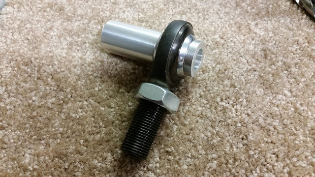
A quick test fit and I was able to see that everything fit exactly as they should.


Now that the rod ends were ready to go, it was time to get back to the LCA. I already had the measurements for how long the rod ends are, as well as how long the tube nut adapters that I'm using as the bungs are. This meant all I had to do was measure on the LCA, mark, and cut.

With everything cut, it was now time to start welding things together! Add the extension in place, the plate for the end of the LCA, and the bung.


In a matter of no time I had them all welded up and looking pretty. Next was to throw the rod ends on to see how they looked!


Of course the arms weren't done here. I still needed to make the plating to weld in the bottom for boxing them in as added strength. With the added length it also adds more leverage to them which could lead to them bending. My extension pieces also don't have the lip on them so that area is a bit of a "weak spot" without any additional bracing.
Before I got to that, first I test fit one of the arms, a knuckle, and got to work on marking out some areas that were going to get some more work. I still needed to add the notch for where the outer tie rod hits and work on figuring up my tension rod setup.

I quick slapped on some junk Megan Racing tension rods I had laying around to see how things were looking and what my clearances where looking like.

Not so good, stock tension rod location was definitely not going to work... I still had a lot more revolutions of the wheel left and I was already drilling the tension rods hardcore. Also on the lead I was hitting the control arm with a lot more travel left.
This was my starting point.


I began working on making some room in all the problem areas. One of the craziest ones I didn't expect to have issues with was the brakes!!! The rotor was hitting the LCA!!!
If you look at the area around the ball joint, you'll see all the trimming I had to do in order to make clearance for the brake rotors. Also I got the tie rod area marked out and began working on the notch.

One other thing you'll notice about the above pictures is that I moved the tension rod over to the sway bar mount hole. Well guess what... that still wasn't even close to enough room.

I played around with some things for a while to get it all better set. I quickly realized my initial idea for a bolt on tension rod might not offer enough clearance. I looked at several pics of different tension rods like the Voodoo ones and noticed even those wouldn't offer enough room!!!
However with some quick thinking I came to a solution. I decided on ditching the stock mounting point and making a new one which would offer much more clearance.
I grabbed some cardboard I had laying around and got started on making a template for the idea. What I decided to do was incorporate the plate bracing for boxing in the LCA and make a new mounting point with it.

Then from the template, I made the plate and got started on the upper portion of the mount. Thankfully I was able to rob a tension rod off of Becca's 510 to use for this.


Once the template was as set up I got to work on making the top piece out of metal. With that I also picked up a nice shoulder bolt which fits so perfectly snug that it will prevent any bit of play from happening.


Really happy with how everything was looking so far, I quick robbed one of Becca's tension rods again so I could use it for some test fitting.


As luck would have it, the tension rods surprisingly were almost the exact length I was needing. So that was great! As for the not so great, the wheel was hitting the plate so I couldn't give it the nice cool curved look I had going on, instead I had to chop it a bit more for some added clearance...Something that at this point felt like it was never ending.

After trimmed some more and test fit once again things appeared like they were good to go. So I moved on to quickly making up the final pieces of the LCA plating.

Then before I got to work on running the welder again I also chopped some tubing to size and got the tension rods all ready to go.

With everything all ready to go it was time to pull the trigger on one of those sexy blue machines again and melt some metal!


Here you have it, my super high clearance tension rod setup was now complete!!!

Time to test fit everything once again to see how it was looking.

Started with cranking the wheel and checking to see how the trailing wheel clearance was looking.

This is when I encountered something I didn't even think would be a problem. An issue I've never heard of someone experiencing. I had thought about it being a potential issue but didn't worry too much about it since I didn't think it would actually end up being one.
The tie rod was hitting the LCA...ON TRAILING!!!

This however gave me a stopping point. So I now knew what maximum trailing angle was going to be for the way everything was currently setup. With that known I was able to look at my tension rod clearance and see if I had done good.
Thankfully it all cleared, but not by much!!! Definitely going to need to add some more clearance to the next ones I do. After all I don't plan on running my little baby 205/40r17 tire forever!


With the arms all welded up and the super high clearance tension rods complete, it was time to get back to the LCA notch so I could get my lead angle where it should be.

I spent a good amount of time slowly grinding away at this spot to get it to where I needed. I didn't want to do too much and make the arm be really weak in that area, but at the same time I didn't want to not do enough and loose steering angle because of it. So I took my time on it and got it to where I thought it was perfect.
Once I knew the amount I then cut it into a more workable shape and welded in some plating to finish the notch off.


The last and final step. Knock out the old shitty ball joint and put in some brand spanking new Moog ones! This was probably the most frustrating part out of everything. The parts store tools were crap and didn't fit the ball joints properly. I had to do some pretty redneck style things, but in the end I got it to work out and the new ball joints were installed. Finally after all this time spent working I had the LCA complete!


Just like that the arms were all finished up and ready to be installed on the car. Now I could get a good idea of what the completed kit was going to be like.
One thing I still had left to do is work on the steering rack relocation. The only issue was I was just 2 days away from a drift event!!! So unfortunately there just wasn't enough time to do the steering rack and I had to get the car together if I was going to make it. I was at least lucky about one thing ,the wheels weren't hitting the tie rods at lock, which really surprised me. Although, with just a 7" wide wheel and an effective offset of around 0, it really isn't all that surprising. I practically have bicycle wheels on the car.


The next morning I was able to do a quick alignment and then drive it to work. One thing I was really excited to see, is how little of camber I was able to have. I don't even have my camber plates at maximum adjustment either! Pretty crazy for a 2.25" extension!


I was unbelievably pleased with the way the car drove. My ackerman angle was less than what it had been with my GKtech knuckles, the steering was a lot quicker, and with the reduction in camber I had a lot more front grip going on. So far, things were a success, and all systems were go for the drift event, aside from needing to do a little bit more alignment work on the car. It was dog trailing a bit and the rear needed some going over, that was something I would have to get done at the track however. The second I got home from work I quickly ran to U-Haul to pick up a trailer and began packing so I could leave first thing in the morning.


The event was a great success! Tons of drivers, a lot of new people I've never had the chance to drive with, and whole lot of tandem runs! The car drove better than ever before, and with the big angle gains I had made over my old GKtech knuckles, I was able to throw it really deep and really start pushing some seriously good angle.
Once back from the event I looked over the car to see how everything was looking. I sure did abuse it a lot that day. Ramped some rumble strips, did some crazy dirt drops, and even slapped my frame on a rumble strip as well. Thankfully everything held up and the only real damage was the tires.
I always like to look over my tires after an event, the way they wear and the other markings on them will tell you a lot about what's going on. One of the things I noticed with mine is that my front right tire had a lot of wear going on, I could see there was a lot of scrub by just looking at them.

This told me my ackerman angle wasn't at all ideal. This amount of scrub shouldn't be showing up after just a days worth of drifting. So I knew for sure I needed to move my rack forward, not just to prevent overcentering (which I had some at full lock) but to make better use of my tires. This would mean more grip, less scrub, more speed, and a longer tire life.
I immediately got to work. Grabbed my spare subframe, stripped everything off of it, and gave it a good cleaning!


Based on the math I had done for the setup, I already had the figures for how much I needed to move the rack forward to obtain the ackerman angle I was after. It worked out to be a rather nice number, 3/4" or just shy of 20mm.
I marked everything out and then made my cut.


One thing to note for anyone doing this themselves. Before you cut anything make a center mark on the subframe. This way, after it's all been cut and trimmed, when you go to weld it back together you'll get the rack mounts centered so your rack positioning will be right. It's not really needed but when I do something I like to keep things nice and centered.
With everything cut, next was to do the trimmings. It just so happened to work out that the two holes going through the subframe were right at 3/4"! Was really nice having those there, they worked out to be great markers for ensuring that the cuts and trimmings were nice and straight so the rack wouldn't end up crooked which would not be a good thing!

Along with trimming the subframe in the center, I also had to trim some areas on the rack mounts so everything would fit together properly.


With all the trimming complete it was now time to weld it up!


One thing I would like to point out about the bottom. Make sure you don't forget to trim the access holes for bolting the rack mounting brackets on. If you don't trim the area you won't be able to get a socket in there at the right angle to get it on the bolt. You can always trim it after welding but its a lot easier if you do it before.

Off with the old subframe, and on with the newly modified one! Installation of it was a breeze. Just support the motor with a jack, unbolt the engine mounts, steering rack, LCA, and lastly the subframe bolts holding it up. From there it simply fell right out. The new one went right up into place, and everything was able to simply bolt right back together. One concern I had was that the steering linkage wasn't going to reach or would bind from having had the rack moved forward. However that wasn't an issue at all which was great news!

Not long after installing the subframe there was another drift event that came up. Time to get some more seat time in and see how the improvements felt.
Just driving to and from work for a couple days I could already tell that this little thing of simply moving the rack forward had made a great change. There was definitely more grip up front, and the response was unbelievably quick. This had me super excited to get out to the track and do some driving.
Out on the track things felt superb, it's amazing how much of a difference I could feel. Before I had never really noticed how much the front seamed to "drag", now it felt so much more free.

Sadly as I was coming up on mid day my luck had run out. On initiation the car kept going straight and went off in the grass. Driving back into the pits the steering wheel was incredibly crooked and turning was a challenge to do. Something was definitely broken.
Back in the pits with the car in the air the problem was quickly discovered. The LCA had buckled where the rod end conversion was done.


Looks like I had a weak spot to take care of. Once home I removed the arms and got to work on assessing the damage.


It would appear that 1/8" material wasn't strong enough for the end plating that the bungs were welded to. Simple solution, cut them off and replace them with something thicker. I concluded that 1/4" should work nicely. I placed an order for some new replacement bungs and made some new plating.


With the plates made and bungs ready to go it was time to put it all together and weld them up.


In a matter of no time at all the LCA were repaired and ready to go back on the car.

All better and good as new! Just needed to go take it for a test drive, which meant some drifting with my homies!
Had a crazy night out with them and might have actually had too much fun. Got a bit carried away and wound up going off into some trees and shrubs. The control arms held up great, my wing however, didn't have a very good time. Had an end plate ripped right off of it.


Enough of the story, its time for some figures and to show what has been achieved!
Measuring angle is a quick and easy thing to do, make sure your alignment is good and your steering is pointing straight. Then use a good straight flat object on the wheel, in my case I used one of my toe plates. Mark the ground with some tape showing what is straight. Then all you have to do is turn the wheel all the way left, mark it with tape. Turn all the way right, mark once more. Then use a protractor and measure the angles.

After turning and making your marks this is what you should have.

From here you just gotta use a protractor.
I laid out both sides this way so I could see if there is any variance between turning left and turning right. Also be able to see if there's a difference in ackerman between steering both ways. If one side is far off from the other it would show that something isn't right. Things that could be wrong is an off centered rack, bump stops in different positions, caster settings far off between the two sides, or even a poorly made knuckle where one arms position is different than the others. This is why I was really excited about getting the measurements off my car. It would show me just how accurate and how good of a job I had done with my kit.
Here are the left side figures. Lead angle clocked in at 71 degrees, and trailing angle of 65 degrees.


Now for the right side angles. Lead angle came in at 72 degrees, and trailing of 66 degrees.


Putting the figures together now. Full lock turning left lead angle 71 degrees, trailing angle 66 degrees. Ackerman angle of only 5 degrees at full lock!
Full lock turning right lead angle 72 degrees, trailing angle 65 degrees. Ackerman angle of 7 degrees.
Lead and trailing angle fluctuations of only 1 degree, and ackerman angle fluctuation of only 2 degrees! Angle came in almost spot on!!! Talk about precision, and some killer numbers! The measurements almost matched with the figures that had been done up on paper which leave out a lot of factors that effect steering. I think it's safe to say the formula I had come up with is a good working one indeed!


Now that you've seen all the work, it's time to discuss where I plan to go with it from here, because this isn't where I intend on stopping. The intentions of making a modified kit were to see how it worked out. Its sole purpose is to be a test setup, hence why I never painted the arms and I've let them get all sorts of rusty.
My end goal is to have a complete angle kit from scratch. Complete LCA/tension rod combo, drop knuckles, angle spacers, and high adjustment camber caster plates. I've also been toying around with the idea to do outer tie rods as well, but, I'll just have to take things one day at a time and see where things go. For now, I'm happy with where I'm at and now comes the fun part of designing something from scratch. Hopefully it won't be too long of a project.

Thanks for reading! I'll catch you all in the next post!

One other thing I would like to mention while on the subject of extensions. Be wary of lies! I've seen it where people have claimed to modify LCA to have roll center correction. This is IMPOSSIBLE to do! "Stair stepping" the extension does not effect roll center at all so if you ever see that, just avoid it. Its a very bad thing to do.

Now comes the question of, "how much of an extension should I do?". Well that's entirely up to you and what your setup is. Your setup (wheels, tires, steering angle, etc) will all play a roll in clearance needs. Another thing is performance, in general the longer the arm the better. Of course this is just a general rule of thumb, it doesn't always work like that because if you don't have supporting modifications done to your car, simply extending your arm a lot can cause some very negative effects. Since I have my own custom camber/caster plates which have a far greater amount of adjustment than your typical camber plate I'm able to get away with more of an extension without suffering from serious negative camber. Another thing to keep in mind is that everything is a compromise. While extending your arm provides you with more clearance between your wheels and frame it will also reduce your clearance between your tie rod and ball joint on trailing.
For figuring out what I needed for clearance I rigged up a nice little way to measure things.

This worked out perfectly for me and I was able to figure up a good length to go with. The amount was a bit of a surprise to me but at the same time was somewhat expected. My rough estimate with running some numbers came out to right around the same range, 2.25".
With a length now determined it was time to move on to the next step. Getting the rod end conversion ready to go. For rod ends I went with all QA1 parts using their Chromoly PTFE lined ones. These are incredibly strong and are also self lubricating with being PTFE lined. This means no worries of them breaking, will have a good amount of life to them, and require absolutely no maintenance with lubrication. The same rod ends where used for Becca's 510 LCA and I absolutely love them! On top of using these for replacing the bushings, I also decided to use them for the tension rods as well. This keeps everything more simplistic and allows me to get away with carrying less parts for spares since everything will be interchangeable.

I should point out Becca had ordered some parts for her V2 LCA at the same time as I did my order so there's a few extra parts in that pic.
With the rod ends in hand it was now time to work on making them compatible with my car. This meant I needed to make some spacers to go in them so they would bolt up properly to the mounting points. After a few minutes spent with a caliper in hand I had all the measurements I needed and was able to quickly draw up a sketch of what to make.
I purchased some 6061 aluminum rods then called up my good friend Keith for his assistance in getting these parts turned.

In a matter of no time we had em turned and ready for install! I also made the tension rod spacers at the same time, which I made offset in order to add some additional clearance of the tension rods. After all, every millimeter counts!!!
A quick test fit and I was able to see that everything fit exactly as they should.
Now that the rod ends were ready to go, it was time to get back to the LCA. I already had the measurements for how long the rod ends are, as well as how long the tube nut adapters that I'm using as the bungs are. This meant all I had to do was measure on the LCA, mark, and cut.

With everything cut, it was now time to start welding things together! Add the extension in place, the plate for the end of the LCA, and the bung.


In a matter of no time I had them all welded up and looking pretty. Next was to throw the rod ends on to see how they looked!


Of course the arms weren't done here. I still needed to make the plating to weld in the bottom for boxing them in as added strength. With the added length it also adds more leverage to them which could lead to them bending. My extension pieces also don't have the lip on them so that area is a bit of a "weak spot" without any additional bracing.
Before I got to that, first I test fit one of the arms, a knuckle, and got to work on marking out some areas that were going to get some more work. I still needed to add the notch for where the outer tie rod hits and work on figuring up my tension rod setup.

I quick slapped on some junk Megan Racing tension rods I had laying around to see how things were looking and what my clearances where looking like.
Not so good, stock tension rod location was definitely not going to work... I still had a lot more revolutions of the wheel left and I was already drilling the tension rods hardcore. Also on the lead I was hitting the control arm with a lot more travel left.
This was my starting point.


I began working on making some room in all the problem areas. One of the craziest ones I didn't expect to have issues with was the brakes!!! The rotor was hitting the LCA!!!
If you look at the area around the ball joint, you'll see all the trimming I had to do in order to make clearance for the brake rotors. Also I got the tie rod area marked out and began working on the notch.

One other thing you'll notice about the above pictures is that I moved the tension rod over to the sway bar mount hole. Well guess what... that still wasn't even close to enough room.
I played around with some things for a while to get it all better set. I quickly realized my initial idea for a bolt on tension rod might not offer enough clearance. I looked at several pics of different tension rods like the Voodoo ones and noticed even those wouldn't offer enough room!!!
However with some quick thinking I came to a solution. I decided on ditching the stock mounting point and making a new one which would offer much more clearance.
I grabbed some cardboard I had laying around and got started on making a template for the idea. What I decided to do was incorporate the plate bracing for boxing in the LCA and make a new mounting point with it.

Then from the template, I made the plate and got started on the upper portion of the mount. Thankfully I was able to rob a tension rod off of Becca's 510 to use for this.


Once the template was as set up I got to work on making the top piece out of metal. With that I also picked up a nice shoulder bolt which fits so perfectly snug that it will prevent any bit of play from happening.


Really happy with how everything was looking so far, I quick robbed one of Becca's tension rods again so I could use it for some test fitting.


After trimmed some more and test fit once again things appeared like they were good to go. So I moved on to quickly making up the final pieces of the LCA plating.

Then before I got to work on running the welder again I also chopped some tubing to size and got the tension rods all ready to go.
With everything all ready to go it was time to pull the trigger on one of those sexy blue machines again and melt some metal!


Here you have it, my super high clearance tension rod setup was now complete!!!
Time to test fit everything once again to see how it was looking.
Started with cranking the wheel and checking to see how the trailing wheel clearance was looking.
This is when I encountered something I didn't even think would be a problem. An issue I've never heard of someone experiencing. I had thought about it being a potential issue but didn't worry too much about it since I didn't think it would actually end up being one.
The tie rod was hitting the LCA...ON TRAILING!!!
This however gave me a stopping point. So I now knew what maximum trailing angle was going to be for the way everything was currently setup. With that known I was able to look at my tension rod clearance and see if I had done good.
Thankfully it all cleared, but not by much!!! Definitely going to need to add some more clearance to the next ones I do. After all I don't plan on running my little baby 205/40r17 tire forever!
With the arms all welded up and the super high clearance tension rods complete, it was time to get back to the LCA notch so I could get my lead angle where it should be.

I spent a good amount of time slowly grinding away at this spot to get it to where I needed. I didn't want to do too much and make the arm be really weak in that area, but at the same time I didn't want to not do enough and loose steering angle because of it. So I took my time on it and got it to where I thought it was perfect.
Once I knew the amount I then cut it into a more workable shape and welded in some plating to finish the notch off.


The last and final step. Knock out the old shitty ball joint and put in some brand spanking new Moog ones! This was probably the most frustrating part out of everything. The parts store tools were crap and didn't fit the ball joints properly. I had to do some pretty redneck style things, but in the end I got it to work out and the new ball joints were installed. Finally after all this time spent working I had the LCA complete!


Just like that the arms were all finished up and ready to be installed on the car. Now I could get a good idea of what the completed kit was going to be like.
One thing I still had left to do is work on the steering rack relocation. The only issue was I was just 2 days away from a drift event!!! So unfortunately there just wasn't enough time to do the steering rack and I had to get the car together if I was going to make it. I was at least lucky about one thing ,the wheels weren't hitting the tie rods at lock, which really surprised me. Although, with just a 7" wide wheel and an effective offset of around 0, it really isn't all that surprising. I practically have bicycle wheels on the car.

The next morning I was able to do a quick alignment and then drive it to work. One thing I was really excited to see, is how little of camber I was able to have. I don't even have my camber plates at maximum adjustment either! Pretty crazy for a 2.25" extension!


I was unbelievably pleased with the way the car drove. My ackerman angle was less than what it had been with my GKtech knuckles, the steering was a lot quicker, and with the reduction in camber I had a lot more front grip going on. So far, things were a success, and all systems were go for the drift event, aside from needing to do a little bit more alignment work on the car. It was dog trailing a bit and the rear needed some going over, that was something I would have to get done at the track however. The second I got home from work I quickly ran to U-Haul to pick up a trailer and began packing so I could leave first thing in the morning.


The event was a great success! Tons of drivers, a lot of new people I've never had the chance to drive with, and whole lot of tandem runs! The car drove better than ever before, and with the big angle gains I had made over my old GKtech knuckles, I was able to throw it really deep and really start pushing some seriously good angle.
Once back from the event I looked over the car to see how everything was looking. I sure did abuse it a lot that day. Ramped some rumble strips, did some crazy dirt drops, and even slapped my frame on a rumble strip as well. Thankfully everything held up and the only real damage was the tires.
I always like to look over my tires after an event, the way they wear and the other markings on them will tell you a lot about what's going on. One of the things I noticed with mine is that my front right tire had a lot of wear going on, I could see there was a lot of scrub by just looking at them.

This told me my ackerman angle wasn't at all ideal. This amount of scrub shouldn't be showing up after just a days worth of drifting. So I knew for sure I needed to move my rack forward, not just to prevent overcentering (which I had some at full lock) but to make better use of my tires. This would mean more grip, less scrub, more speed, and a longer tire life.
I immediately got to work. Grabbed my spare subframe, stripped everything off of it, and gave it a good cleaning!


Based on the math I had done for the setup, I already had the figures for how much I needed to move the rack forward to obtain the ackerman angle I was after. It worked out to be a rather nice number, 3/4" or just shy of 20mm.
I marked everything out and then made my cut.


One thing to note for anyone doing this themselves. Before you cut anything make a center mark on the subframe. This way, after it's all been cut and trimmed, when you go to weld it back together you'll get the rack mounts centered so your rack positioning will be right. It's not really needed but when I do something I like to keep things nice and centered.
With everything cut, next was to do the trimmings. It just so happened to work out that the two holes going through the subframe were right at 3/4"! Was really nice having those there, they worked out to be great markers for ensuring that the cuts and trimmings were nice and straight so the rack wouldn't end up crooked which would not be a good thing!

Along with trimming the subframe in the center, I also had to trim some areas on the rack mounts so everything would fit together properly.


With all the trimming complete it was now time to weld it up!


One thing I would like to point out about the bottom. Make sure you don't forget to trim the access holes for bolting the rack mounting brackets on. If you don't trim the area you won't be able to get a socket in there at the right angle to get it on the bolt. You can always trim it after welding but its a lot easier if you do it before.

Off with the old subframe, and on with the newly modified one! Installation of it was a breeze. Just support the motor with a jack, unbolt the engine mounts, steering rack, LCA, and lastly the subframe bolts holding it up. From there it simply fell right out. The new one went right up into place, and everything was able to simply bolt right back together. One concern I had was that the steering linkage wasn't going to reach or would bind from having had the rack moved forward. However that wasn't an issue at all which was great news!

Not long after installing the subframe there was another drift event that came up. Time to get some more seat time in and see how the improvements felt.
Just driving to and from work for a couple days I could already tell that this little thing of simply moving the rack forward had made a great change. There was definitely more grip up front, and the response was unbelievably quick. This had me super excited to get out to the track and do some driving.
Out on the track things felt superb, it's amazing how much of a difference I could feel. Before I had never really noticed how much the front seamed to "drag", now it felt so much more free.

Sadly as I was coming up on mid day my luck had run out. On initiation the car kept going straight and went off in the grass. Driving back into the pits the steering wheel was incredibly crooked and turning was a challenge to do. Something was definitely broken.
Back in the pits with the car in the air the problem was quickly discovered. The LCA had buckled where the rod end conversion was done.


Looks like I had a weak spot to take care of. Once home I removed the arms and got to work on assessing the damage.


It would appear that 1/8" material wasn't strong enough for the end plating that the bungs were welded to. Simple solution, cut them off and replace them with something thicker. I concluded that 1/4" should work nicely. I placed an order for some new replacement bungs and made some new plating.


With the plates made and bungs ready to go it was time to put it all together and weld them up.


In a matter of no time at all the LCA were repaired and ready to go back on the car.

All better and good as new! Just needed to go take it for a test drive, which meant some drifting with my homies!
Had a crazy night out with them and might have actually had too much fun. Got a bit carried away and wound up going off into some trees and shrubs. The control arms held up great, my wing however, didn't have a very good time. Had an end plate ripped right off of it.

It took a good while of searching around in the dark, but I did retrieve the lost end plate!


Enough of the story, its time for some figures and to show what has been achieved!
Measuring angle is a quick and easy thing to do, make sure your alignment is good and your steering is pointing straight. Then use a good straight flat object on the wheel, in my case I used one of my toe plates. Mark the ground with some tape showing what is straight. Then all you have to do is turn the wheel all the way left, mark it with tape. Turn all the way right, mark once more. Then use a protractor and measure the angles.

After turning and making your marks this is what you should have.

From here you just gotta use a protractor.
I laid out both sides this way so I could see if there is any variance between turning left and turning right. Also be able to see if there's a difference in ackerman between steering both ways. If one side is far off from the other it would show that something isn't right. Things that could be wrong is an off centered rack, bump stops in different positions, caster settings far off between the two sides, or even a poorly made knuckle where one arms position is different than the others. This is why I was really excited about getting the measurements off my car. It would show me just how accurate and how good of a job I had done with my kit.
Here are the left side figures. Lead angle clocked in at 71 degrees, and trailing angle of 65 degrees.


Now for the right side angles. Lead angle came in at 72 degrees, and trailing of 66 degrees.


Putting the figures together now. Full lock turning left lead angle 71 degrees, trailing angle 66 degrees. Ackerman angle of only 5 degrees at full lock!
Full lock turning right lead angle 72 degrees, trailing angle 65 degrees. Ackerman angle of 7 degrees.
Lead and trailing angle fluctuations of only 1 degree, and ackerman angle fluctuation of only 2 degrees! Angle came in almost spot on!!! Talk about precision, and some killer numbers! The measurements almost matched with the figures that had been done up on paper which leave out a lot of factors that effect steering. I think it's safe to say the formula I had come up with is a good working one indeed!


Now that you've seen all the work, it's time to discuss where I plan to go with it from here, because this isn't where I intend on stopping. The intentions of making a modified kit were to see how it worked out. Its sole purpose is to be a test setup, hence why I never painted the arms and I've let them get all sorts of rusty.
My end goal is to have a complete angle kit from scratch. Complete LCA/tension rod combo, drop knuckles, angle spacers, and high adjustment camber caster plates. I've also been toying around with the idea to do outer tie rods as well, but, I'll just have to take things one day at a time and see where things go. For now, I'm happy with where I'm at and now comes the fun part of designing something from scratch. Hopefully it won't be too long of a project.

Thanks for reading! I'll catch you all in the next post!